Planning for hospital utility failures and recovery

The failure of a major switchgear assembly can impact a portion or all of the system depending upon system configuration.
Health care organizations are expected to provide safe and reliable health care to their patients. Planning appropriate response and recovery activities for a failure of the facility’s utility systems is essential to satisfy this expectation.
These systems constitute the operational infrastructure that permits safe patient care to be performed. Some of the most important utilities include mechanical (e.g., heating, ventilation and cooling); electrical (i.e., normal power and emergency power); domestic hot and cold water as well as other plumbing systems; waste; technology systems, including the myriad communications and data-transfer systems; vertical transportation utilities; fire alarm and suppression systems; fuel systems; access control, duress alarm and surveillance systems; medical gases, air and vacuum systems; and pneumatic tube systems.
Although the Centers for Medicare & Medicaid Services (CMS) Emergency Preparedness Final Rule affects all 17 CMS provider types, this article will discuss only the CMS Conditions of Participation Section 482.15 pertaining to hospital emergency preparedness for all hazards. One can infer that within the words “all hazards,” there is room for external or internal utility failures.
Within Emergency Preparedness Final Rule Subsection 482.15 (b) Policies and procedures, is the requirement that “at a minimum, the policies and procedures must address the following: “the provision of subsistence needs for staff and patients, whether they evacuate or shelter in place, include, but are not limited to” elements including “alternate sources of energy to maintain the following: temperatures to protect patient health and safety and for the safe and sanitary storage of provisions; emergency lighting; fire detection, extinguishing and alarm systems; and sewage and waste disposal.”
Potential failure points
Failures can occur at the utility source, at a major utility distribution point, at downstream utility distribution points or at local utility usage points.
A utility system source could be internal, such as a fire alarm control panel, a pneumatic tube blower, one or more medical gas system storage tanks, equipment located within an elevator machine room, a medical air compressor, a medical vacuum pump, a fuel oil storage tank, an emergency generator, a chiller or a boiler. The utility system source also could be external, such as the electrical utility lines serving a health care facility, the local water utility service to a building, the internet connection from an off-site data center, or the local telephone or communications network serving a facility.

Metering results often can be useful in assessing the impacts of partial utility failures.
Major utility distribution points could be a main electrical normal power switchgear room, a multiple-generator paralleling switchgear assembly, the water meter and water mains, the main chilled water piping that connects multiple chillers, the major steam piping that connects multiple boilers, a telephone switch room, a data switch room, the connection between multiple medical gas tanks, multiple medical vacuum pumps, or multiple medical air compressors, depending upon the system.
And further downstream, there are still very impactful distribution points. These may include electrical risers, operating room critical branch automatic transfer switches, emergency motor control centers serving isolation room exhaust fans, domestic hot and cold water risers, major chilled water or steam piping runs, air handlers serving acute care spaces, building automation systems controlling the facility’s HVAC equipment, emergency radio system repeaters, data system risers, medical gas, air and vacuum risers, and so forth.
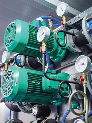
Local distribution locations and equipment can include items such as a patient floor mechanical room, electrical closet, information technology data closet, medical gas zone valve panel, isolation room exhaust fan, stairwell pressurization fan and so forth.
The generic utility failure plan for many organizations is to consider only the overall failure of a utility, such as loss of water, loss of normal power, loss of a boiler or loss of steam, loss of a chiller or loss of cooling. Although this approach may be sufficient for that specific scenario, it may not serve the organization well when the failure occurs at a major distribution point, another impactful downstream distribution point or more local to the point of care.
Built-in redundancies
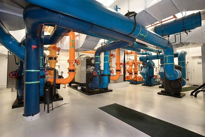
Many hospitals have built-in redundancies within their utility systems. Often, these redundancies are capacity redundancies only, but without distribution redundancies due to capital funding limitations. For example, redundant chillers tied into the same chilled water header can have redundant capacity (e.g., the multiple chillers) but not redundant distribution (e.g., the header, which could be a single common-mode failure point).
You may also like |
| Hospital power system reliability |
| Planning for water outages |
| Ensuring utility plant reliability |
|
|
Another example of the difference between redundant capacity and redundant distribution could be multiple generators tied into the same paralleling switchgear assembly. That paralleling switchgear assembly could be a single common-mode failure point, where the inability to distribute power through the single common-mode failure point exists regardless of the quantity of operating generators. Capacity redundancies often permit equipment (e.g., a chiller, generator or boiler) maintenance or repair without the need for turning off some of the equipment loads. But there are still single failure points that could cause an outage of a major portion of or perhaps the entire utility system.
Organizations considering revisiting their existing utility failure procedures may consider determining response and recovery procedures for the loss of major internal distribution elements as well as the major capacity elements.
Utility failure response
The online Business Dictionary defines organizational memory as “largely undocumented experience, insights, knowledge and skills acquired over the years, passed on to the newcomers through personal contacts, meetings, training courses and mentor-protégé relationships. Organizational memory (unless pooled and recorded in a readily accessible form such as a database) is destroyed through excessive downsizing, frequent layoffs, unmanaged employee attrition and/or disasters.”
A subset of this concept could be the organizational facility memory. This organizational facility memory can be lost due to employee retirement or other attrition causes. The unavailability of organizational facility memory can have a negative impact on an organization’s ability to respond and recover effectively from utility failures, particularly if the specific utility failure cause is not one that was previously included in failure procedures.
Sometimes organizational facility memory can include temporary measures such as backups or spare equipment that were put into place to facilitate previous planned equipment outages or previous repairs. As stated in the American Society for Healthcare Engineering’s 2014 ASHE monograph on “Managing Hospital Electrical Shutdowns,” which can be accessed online at www.ashe.org/management_monographs/, it is often helpful to capture such temporary measures and get that knowledge into the appropriate failure procedures.

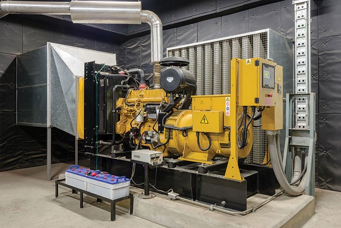
Failure of one generator can be mitigated by having a multiple-generator paralleling system.
Failure procedures can be simple or complex. The simple failure procedures often describe the planned-for utility failure as the “loss of electricity,” “loss of cooling” or “loss of water.” The simple procedures can work if the responding personnel have the necessary facility memory to deal with unplanned-for internal failures. The simple procedures are often short and do not provide many details of the steps necessary for effective response and recovery from partial internal failures.
More complex procedures may identify the necessary steps to deal with major equipment loss (i.e., a chiller, boiler or switchgear assembly). Complex procedures also may identify the necessary steps to deal with major distribution failures, such as the failure of a main chilled-water header, a main steam header, an electrical riser or a main oxygen riser. The more complex procedures can get in the way of some optional response steps, but can be useful if they are based upon organizational facility memory.
When reviewing existing utility failure procedures or planning to create more comprehensive utility failure procedures, it is recommended that organizations conduct a vulnerability analysis to determine each utility’s most impactful vulnerabilities. Those vulnerabilities may be unexpected locations or failure types that can have a greater impact on patient care than might otherwise be anticipated.
They often are high-level distribution points or points where a single failure can have multiple ramifications, such as the failure of a common power source or the existence of a single equipment location housing redundant equipment. The vulnerabilities also may be due to lack of maintenance on important equipment.
It may also be helpful to prepare a gap analysis to determine areas where existing vulnerabilities can obstruct effective utility failure response. The gap analysis can help the organization to determine how to deal with those vulnerabilities in the short term until they can be corrected. A useful gap analysis can ask and answer these four questions: “Where are we now?” “Where do we want to be?” “How do we get there?” and “How do we do this?” A utility failure gap analysis can be helpful when it responds to the findings of a utility vulnerability analysis.
Finally, certain types of activities may be a necessary utility failure response step, but do not often find their way into the utility failure procedures. One example for Joint Commission-
accredited hospitals is the required response to life safety or fire safety system deficiencies — the Interim Life Safety Measures assessment if the deficiency is not corrected immediately.
Another example for infection control equipment failure is the need to mitigate the resulting increased infection risk until the condition has been corrected. This response may include performing an infection control risk assessment. Any other utility failure impacts on patient care and patient safety as well as staff safety also should be mitigated.
Useful resources
Numerous technical resources are available for organizations wishing to review and validate their existing utility failure procedures.
Perhaps one of the best new ones available to organizations interested in enhancing their existing utility failure procedures is a website established by the Department of Health & Human Services’ Assistant Secretary for Preparedness and Response (ASPR).
According to the site, the ASPR Technical Resources, Assistance Center and Information Exchange was created to meet the information and technical assistance needs of regional ASPR staff, health care coalitions, health care entities, health care providers, emergency managers, public health practitioners and others working in disaster medicine, health care system preparedness and public health emergency preparedness.
Given the importance of health care utility services, this type of assistance is vital.
David L. Stymiest, P.E., CHFM, CHSP, FASHE, is a senior consultant at Smith Seckman Reid, Nashville, Tenn., specializing in facilities engineering and regulatory compliance. He can be reached at DStymiest@SSR-inc.com. Although Stymiest is a primary voting member and past chairman of the National Fire Protection Association (NFPA) Technical Committee on Emergency Power Supplies, the views and opinions expressed in this article are his and shall not be considered the official position of NFPA or any of its technical committees and shall not be considered to be, nor be relied upon as, a formal interpretation. Readers are encouraged to refer to the entire text of all referenced documents.


